WALL SENSORS
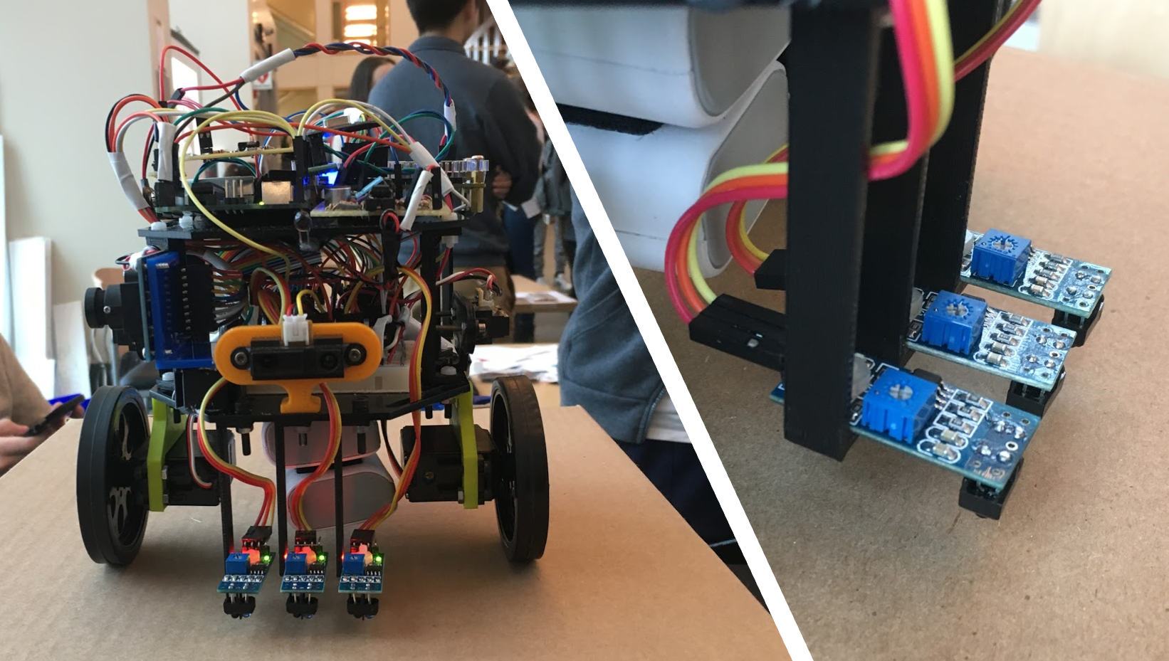
We mounted 3 short distance analog distance sensors on the front and sides of Slash. The mounting components were 3D printed so we chose colors to maintain a symmetric design.
We mounted 3 short distance analog distance sensors on the front and sides of Slash. The mounting components were 3D printed so we chose colors to maintain a symmetric design.
We won 3 Analog/Digital line sensors in 3400 lecture competition. These were advantageous because they allowed manual hardware thresholding on their digital pins through a potentiometer mounted on each. This made tuning and testing much easier because the LEDs on each outputted if they were on a white or grey surface, allowing for tuning on any surface we tested on and removing the need to reset code every time the line sensors had a problem. We spent a lot of time choosing a mounting height but settled on about 7.5mm from the ground because it was able to consistently read lines correctly even on dirty surfaces.

We mounted all three sensors next to each other in the front for a number of reasons. The first was that by mounting them farther forward, we were able to turn more consistently because the sensors were away from intersections for a longer time. In addition, by making the distance between each sensor slightly less than the width of a line, we allowed the possibility for two sensors to be triggered simultaneously. This allowed 6 different cases for the robot’s position: Left, Left-Mid, Mid, Mid-Right, Right, None. For the Left-Mid and Mid-Right instead of turning one servo off and just using the other to get back on track as other teams did, we slowed down one in order to slowly get back on the line, creating a much smoother line following pattern. This was especially useful with the integration of our faster servos.
We switched out the normal Parallax continuous rotation servos with High Speed Parallax continuous rotation servos and mounted them in the front quarter of our chassis. We initially wanted to increase our robot’s speed, recognizing that a faster robot would be able to map more of the map and score better. We considered motors but decided that with our limited time, the simplest and best solution would be to use higher speed versions of wervos we already had. They were 3 times faster and only required a new power source.

We had 3 seperate power requirements. The FPGA and Arduino required 5V, the Servos required 6-8V, and the IR hat required 9V. The 5V source we had available fed from a USB port so we decided to connect each device to a separate source. The servos said that they required 6-8V but we tried using a 9V battery so that we didn’t have to regulate. This ended working so we wired each servo to a battery in order to supply each with maximum power. We also wanted to make the IR hat module in order to test so we attached that to its own 9V battery.

Since a low center of mass allowed for increased reliability and limited tipping at higher speeds, we attached both 5V voltage sources to the bottom of the robot, as close to the ground as possible. We connected the 9V batteries on the bottom of the robot directly behind each servo for easy access and replacement. Since the IR hat was on top, we mounted that to directly opposite the FPGA, close to the hat without sticking out.
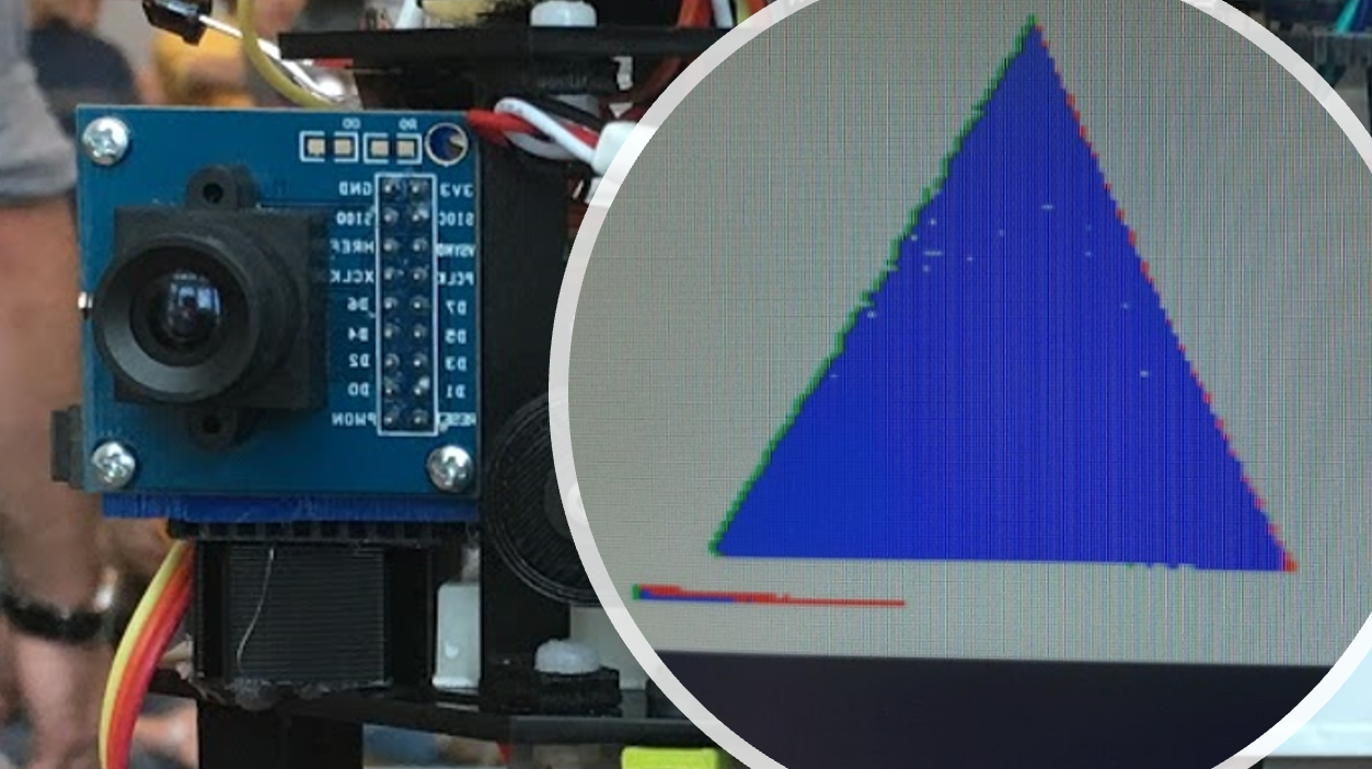
We mounted our camera near the front of our robot, pointing to the right, exactly 4.25” off of the ground. We mounted at the front so that the camera was directly above the line sensors. This meant that when the robot stopped at the intersection, the camera would be aligned with the line and facing a treasure if there was one there. The treasures were also 4.25” off of the ground so the they would be fully in frame. We faced right because our DFS program prioritized right turns. We connected all wiring from the camera to a breadboard mounted at the back of the robot. This helped section off all camera components with FPGA and 3.3V breadboard both at the back. All connections and software on the FPGA and camera communicated properly with the arduino indicating proper wiring.

We prioritized adaptable systems so we made as little permanent as possible. Components were velcroed and screwed at the beginning of the process and taped near the end. However, all components were stable. Our robot could be shaken heavily and operate properly. This was advantageous with the faster system.
The following is a circuit diagram for the main Arduino.

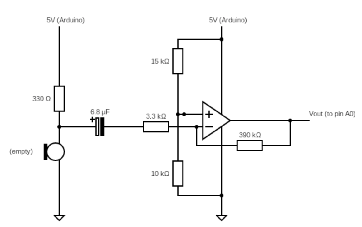
The following is a circuit diagram for the audio amplifier circuit

The following is a circuit diagram for infrared amplifier circuit.

The following is a circuit diagram for the mux between the audio and the IR circuit.

Copyright © 2016 - All Rights Reserved - Domain Name
Template by OS Templates