• Home
  • Pages
    • Labs
    • Milestones
    • Team
    • Documents
  • Gallery
  • Robot Design
  • Software Design
Robots 'N' Roses Software Design

Maze exploration algorithm

Slash used DFS with BFS backtracking to explore the maze.

Data Structures

We used a struct node to keep track of each intersection in the maze (Figure 1). Each node contains fields node_dir and visited. Node_dir keeps track of the direction the robot was facing when it first visited that node. Visited is a bool that keeps track of whether the node was visited or not. We keep track of each node in maze, a 9x9 array. Nodes are identified by their indices in the matrix (eg. intersection at y = 1 and x = 2 is the node at maze[1][2]). We were about to add a 1 byte field, walls, to our node struct to store the location of walls at each node. This was supposed to prevent Slash from detecting false walls or not detecting actual walls while backtracking. However, after running the robot in a practice maze multiple times, we noticed that backtracking corrects the nodes’ wall placement if Slash’s wall detection messes up at the start of a run.

DFS Logic

We added logic to detect if a node position is out of range while deciding which direction to turn. A direction is not blocked if there is no wall, the adjacent node in that direction has not been visited, and the node is not out of bounds (Figure 12).

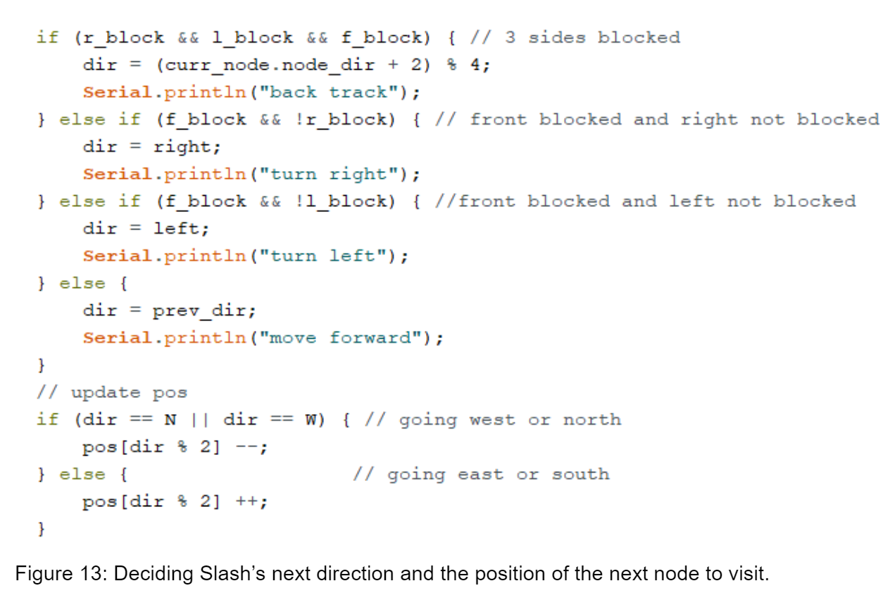
After deciding which paths are blocked, we decide which cardinal direction Slash will be facing and the next node he will visit (Figure 13).
Treasure Detection (Arduino Side)

We read the values sent to pins 8 and A0, and wrote them to variables shape0 and shape1 respectively (Figure 2). If shape1 exceeds a threshold value, we set shape1 to 1. These values are sent through the radio. The base station then reads shape0 and shape1 to determine the treasure’s shape (Figure 3).

RF Transmission

When Slash detects an intersection, before running DFS, he sends his position (x, y), and the location of the four walls at that location. We were going to send the shape of the treasure detected; however, adding treasure detection bits messed up the rest of the transmitted packet.

After receiving the transmitted value, the base station decodes position (x,y) and wall locations (Figure 5) and formats them into a string accepted by the GUI code.

Turning

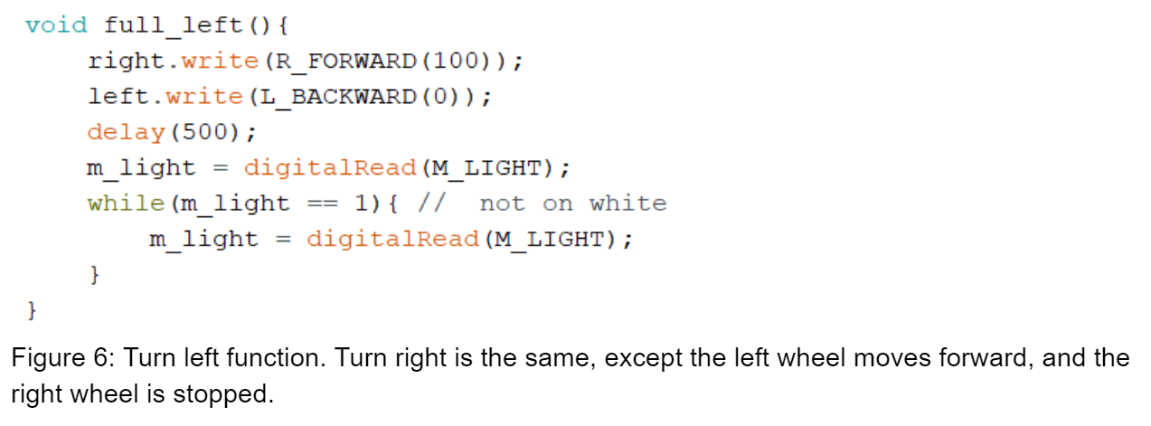
With our new servos, we experimented with different turn functions. At first we tried to turn quickly by moving the wheels at opposite directions; however, this was unreliable because the turn function would finish too early. And Slash would keep moving forward instead. We opted for a slower but more reliable turn by stopping one wheel. After setting the wheel speed and a fixed delay, we keep turning until our middle line sensor reaches a white line (Figure 6).

In our turnaround function, Slash moves backwards for a fixed delay (to leave the intersection), then moves both wheels in opposite directions until the middle line sensor finds a line (Figure 7).

Line Following

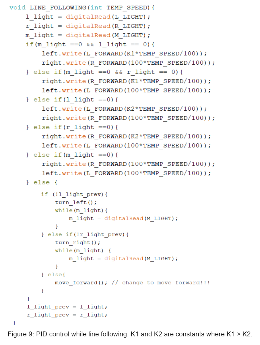
Using 3 line sensors enabled us to have a more efficient PID control (Figure 9). Depending on the degree at which Slash is off the line, we adjust the speed of each wheel. If the middle sensor and a right or left sensor is on the line, Slash is only slightly off course, and we slow down one of the wheels slightly. If the left or right sensor is on the line, the middle sensor is not, Slash is moderately off course, so we slow down one of the wheels moderately. We also keep track of the previous values of both left and right sensors to help Slash get back on track if he is moved completely off course. For example, if the previous value of the left sensor is 0 (the left sensor was on the line last iteration of the main loop), and all line sensors currently read 1, Slash will turn left until the middle sensor reaches a line.

Start Condition

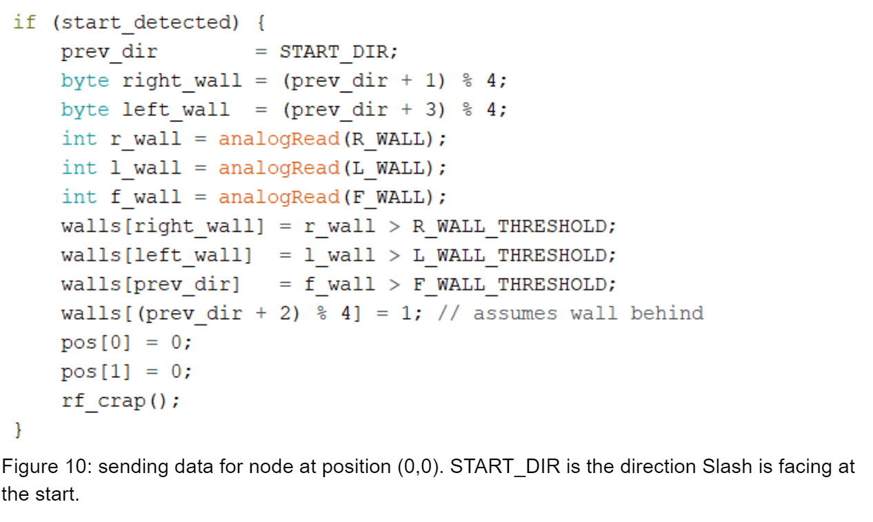
Slash needs to detect a 660Hz tone or the emergency button to start running. In the main loop, we call a function check_for_start that looks out for each of these conditions. We use analogRead to detect if the emergency button was pushed. Otherwise, we use the FFT library to collect data from the microphone. We read bin 5 of the ADC samples. If that value is greater than a threshold, we increment a counter. Once the counter reaches 10, the 660Hz signal was detected. We use a counter to prevent false starts. After a start condition is satisfied, proper registers used for analogRead are restored. Because Slash does not start on an intersection, we immediately detect walls and send maze data for node at position (0,0) to the GUI (Figure 10).

IR Detection

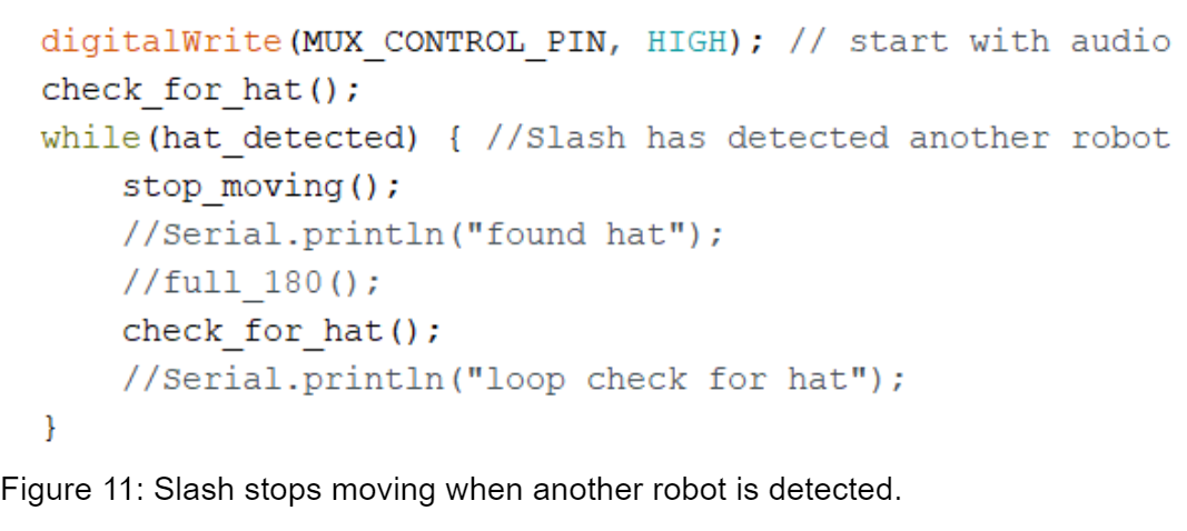
We also used the FFT library to detect other robots. If a robot is detected, Slash with stop moving until the other robot moves out of range.

We also mux IR detection and audio 660Hz detection to conserve analog pins. We set the mux select to 1 while using IR detection and 0 while using audio detection.

Copyright © 2016 - All Rights Reserved - Domain Name

Template by OS Templates